Follow lines car
视频教程20 - 巡线小车:https://singtown.com/learn/50037/
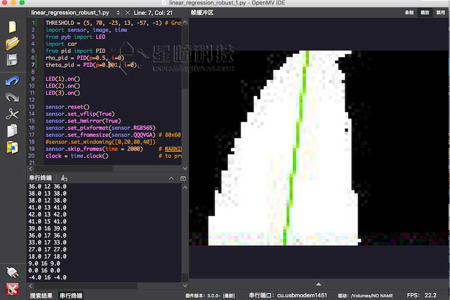
This example shows off how to use the get_regression() method on your OpenMV Cam to get the linear regression of a ROI. Using this method you can easily build a robot which can track lines which all point in the same general direction but are not actually connected.
This example can be used for robots to patrol the line, and the effect is good.
The tracking balls
视频教程9 - 追小球的小车:https://singtown.com/learn/49239/
Prepare for the material:
OpenMV Cam x1:

Car’s base board printed in 3D:

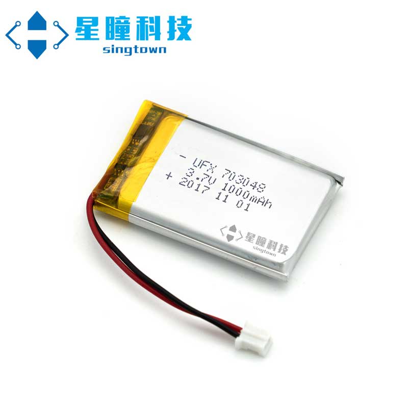
- 3.7V li batteryx1:
- TB6612 motor driving shield x1:

- Bull’s-eye wheel x2:

- N20 DC motor x2(including fixed seat and wheel):

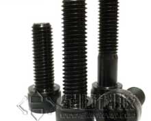
- M3*20 screw and nut x2:
- M2*4 Self-tapping screws x2

Wire and test motor
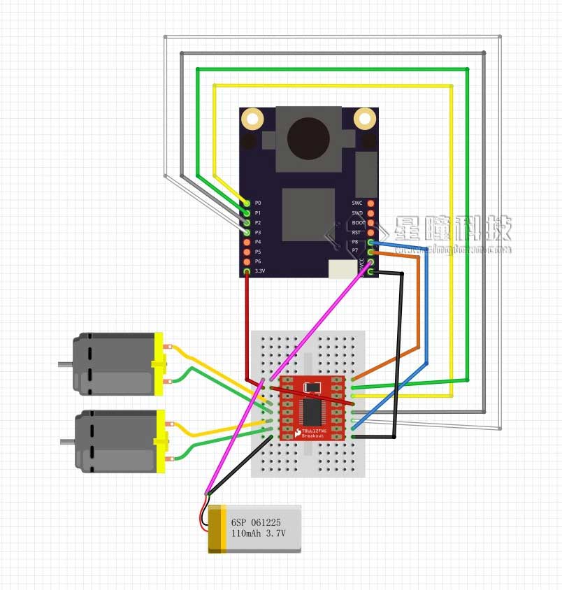
write car’s module
First of all, I need to answer the question that why write module since driving motor directly is not so hard. That’s because in this way, the code can be used repeatedly better The logic being controlled is independent on the structure of car. For different car, all you need to do is that changing the module of car. car.py
from pyb import Pin, Timer
inverse_left=False  #change it to True to inverse left wheel
inverse_right=False #change it to True to inverse right wheel

ain1 =  Pin('P0', Pin.OUT_PP)
ain2 =  Pin('P1', Pin.OUT_PP)
bin1 =  Pin('P2', Pin.OUT_PP)
bin2 =  Pin('P3', Pin.OUT_PP)
ain1.low()
ain2.low()
bin1.low()
bin2.low()

pwma = Pin('P7')
pwmb = Pin('P8')
tim = Timer(4, freq=1000)
ch1 = tim.channel(1, Timer.PWM, pin=pwma)
ch2 = tim.channel(2, Timer.PWM, pin=pwmb)
ch1.pulse_width_percent(0)
ch2.pulse_width_percent(0)

def run(left_speed, right_speed):
    if inverse_left==True:
        left_speed=(-left_speed)
    if inverse_right==True:
        right_speed=(-right_speed)

    if left_speed < 0:
        ain1.low()
        ain2.high()
    else:
        ain1.high()
        ain2.low()
    ch1.pulse_width_percent(abs(left_speed))

    if right_speed < 0:
        bin1.low()
        bin2.high()
    else:
        bin1.high()
        bin2.low()
    ch2.pulse_width_percent(abs(right_speed))
Save the file above as car.py, according toUsage of module, save car.py into OpenMV.
Test code in IDE: main.py
import car

while True:
    car.run(100,100)
See whether the car go straight or not, if not, change inverse left and inverse right on line two and three to make left wheel or right wheel invert.Make sure car goes ahead in a positive direction.
car.run(left_speed, right_speed)有两个参数,一个是左轮子的速度,一个是右轮子的速度。
速度的参数如果是正数,就会向前转,如果是负数,就会向后转,0~100数字越大,速度就越大。
Realize algorithm PID
Algorithm pid is an algorithm used very often, there is a lot about the theory.
https://zh.wikipedia.org/wiki/PID控制器
http://baike.baidu.com/link?url=-obQq78Ur4bTeqA10bIniO6y0euQFcWL9WW18vq2hA3fyHN3rt32o79F2WPE7cK0Di9M6904rlHD9ttvVTySIK
The code is ordinary, I just copy source code of one of the autopilot.
https://github.com/wagnerc4/flight_controller/blob/master/pid.py
It is coped from ArduPilot
https://github.com/ArduPilot/ardupilot
pid.py
from pyb import millis
from math import pi, isnan

class PID:
    _kp = _ki = _kd = _integrator = _imax = 0
    _last_error = _last_derivative = _last_t = 0
    _RC = 1/(2 * pi * 20)
    def __init__(self, p=0, i=0, d=0, imax=0):
        self._kp = float(p)
        self._ki = float(i)
        self._kd = float(d)
        self._imax = abs(imax)
        self._last_derivative = float('nan')

    def get_pid(self, error, scaler):
        tnow = millis()
        dt = tnow - self._last_t
        output = 0
        if self._last_t == 0 or dt > 1000:
            dt = 0
            self.reset_I()
        self._last_t = tnow
        delta_time = float(dt) / float(1000)
        output += error * self._kp
        if abs(self._kd) > 0 and dt > 0:
            if isnan(self._last_derivative):
                derivative = 0
                self._last_derivative = 0
            else:
                derivative = (error - self._last_error) / delta_time
            derivative = self._last_derivative + \
                                     ((delta_time / (self._RC + delta_time)) * \
                                        (derivative - self._last_derivative))
            self._last_error = error
            self._last_derivative = derivative
            output += self._kd * derivative
        output *= scaler
        if abs(self._ki) > 0 and dt > 0:
            self._integrator += (error * self._ki) * scaler * delta_time
            if self._integrator < -self._imax: self._integrator = -self._imax
            elif self._integrator > self._imax: self._integrator = self._imax
            output += self._integrator
        return output
    def reset_I(self):
        self._integrator = 0
        self._last_derivative = float('nan')
同样根据模块的使用,将pid.py保存到OpenMV中。
Adjust parameter, realize following
It is mainly about adjusting two PI parameters,http://blog.csdn.net/zyboy2000/article/details/9418257
THRESHOLD = (5, 70, -23, 15, -57, 0) # Grayscale threshold for dark things...
import sensor, image, time
from pyb import LED
import car
from pid import PID
rho_pid = PID(p=0.4, i=0)
theta_pid = PID(p=0.001, i=0)

LED(1).on()
LED(2).on()
LED(3).on()

sensor.reset()
sensor.set_vflip(True)
sensor.set_hmirror(True)
sensor.set_pixformat(sensor.RGB565)
sensor.set_framesize(sensor.QQQVGA) # 80x60 (4,800 pixels) - O(N^2) max = 2,3040,000.
#sensor.set_windowing([0,20,80,40])
sensor.skip_frames(time = 2000)     # WARNING: If you use QQVGA it may take seconds
clock = time.clock()                # to process a frame sometimes.

while(True):
    clock.tick()
    img = sensor.snapshot().binary([THRESHOLD])
    line = img.get_regression([(100,100,0,0,0,0)], robust = True)
    if (line):
        rho_err = abs(line.rho())-img.width()/2
        if line.theta()>90:
            theta_err = line.theta()-180
        else:
            theta_err = line.theta()
        img.draw_line(line.line(), color = 127)
        print(rho_err,line.magnitude(),rho_err)
        if line.magnitude()>8:
            #if -40<b_err<40 and -30<t_err<30:
            rho_output = rho_pid.get_pid(rho_err,1)
            theta_output = theta_pid.get_pid(theta_err,1)
            output = rho_output+theta_output
            car.run(50+output, 50-output)
        else:
            car.run(0,0)
    else:
        car.run(50,-50)
        pass
    #print(clock.fps())
如果要制作巡线小车的话,只需利用本程序得到的line对象的theta返回值和rho,(theta代表返回线段的角度, rho代表偏移的距离),利用theta和rho来控制小车角度即可。
rho更重要一些,如果不用theta,只用rho也是可以的。
运行效果图: