All kinds of peripherals of pyb
Genaral view
As a single chip,controlling IO port ,IIC, SPI, CAN, PWM and timer is all tolerable.Moreover,using language python is an easy way to transfer them without considering register.
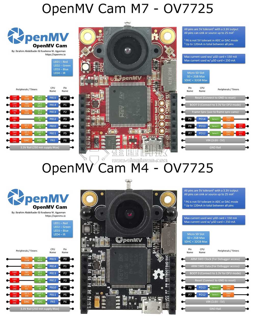
| Tables | OpenMV2(M4) | OpenMV3(M7) |
|---|---|---|
| Pin | 9 | 10 |
| ADC/DAC | 1 | 1 |
| SPI | 1 | 1 |
| I2C | 1 | 2 |
| UART | 1 | 2 |
| Servo | 2 | 3 |
| CAN bus | no | 1 |
| IC | STM32F427 | STM32F765 |
| RAM | 256K | 512K |
| Flash | 1MB | 2MB |
| freq | 180MHz | 216MHZ |
It’s worth noting that:because MicroPython can be in motion in plenty of platforms.The first part of a period of time,module pyb and pyboard are based on STM32,however, with the participation of esp8266 esp32 and series nrf,whose infrustructure is unlike STM32.So module machine is unified instituted officially,which lead to the commonality being higher.Ultimately,pyb will be washed out,but at this moment pyb has more function than machine.In this tutorial,I2C is the only one to use bank machine.
Function in common usage
pyb.delay(50) # delay 50ms
pyb.millis() #Get the number of milliseconds since the start
LED
from pyb import LED

led = LED(1) # 红led
led.toggle()
led.on()#亮
led.off()#灭
LED(1) -> RED LED
LED(2) -> GREEN LED
LED(3) -> BLUE LED
LED(4) -> two IR LED
IO
from pyb import Pin

p_out = Pin('P7', Pin.OUT_PP)#set P7(p_out) output
p_out.high()#set p_out to high level
p_out.low()#set p_out to low level

p_in = Pin('P7', Pin.IN, Pin.PULL_UP)#set P7(p_in) input,and enable pull up resistance
value = p_in.value() # get value, 0 or 1
Servo
from pyb import Servo

s1 = Servo(1) # servo on position 1 (P7)
s1.angle(45) # move to 45 degrees
s1.angle(-60, 1500) # move to -60 degrees in 1500ms
s1.speed(50) # for continuous rotation servos
- Servo(1) -> P7 (PD12)
- Servo(2) -> P8 (PD13)
OpenMV M7 add:
- Servo(3) -> P9 (PD14)
IO Interrupt
from pyb import Pin, ExtInt

callback = lambda e: print("intr")
ext = ExtInt(Pin('P7'), ExtInt.IRQ_RISING, Pin.PULL_NONE, callback)
Timer
from pyb import Timer

tim = Timer(4, freq=1000)
tim.counter() # get counter value
tim.freq(0.5) # 0.5 Hz
tim.callback(lambda t: pyb.LED(1).toggle())
Timer 1 Channel 3 Negative -> P0
Timer 1 Channel 2 Negative -> P1
Timer 1 Channel 1 Negative -> P2
Timer 2 Channel 3 Positive -> P4
Timer 2 Channel 4 Positive -> P5
Timer 2 Channel 1 Positive -> P6
Timer 4 Channel 1 Negative -> P7
Timer 4 Channel 2 Negative -> P8
OpenMV M7 add:
Timer 4 Channel 3 Positive -> P9
PWM
from pyb import Pin, Timer

p = Pin('P7') # P7 has TIM4, CH1
tim = Timer(4, freq=1000)
ch = tim.channel(1, Timer.PWM, pin=p)
ch.pulse_width_percent(50)
ADC
from pyb import Pin, ADC

adc = ADC('P6')
adc.read() # read value, 0-4095
DAC
from pyb import Pin, DAC

dac = DAC('P6')
dac.write(120) # output between 0 and 255
UART
from pyb import UART

uart = UART(3, 9600)
uart.write('hello')
uart.read(5) # read up to 5 bytes
UART 3 RX -> P5 (PB11)
UART 3 TX -> P4 (PB10)
OpenMV M7上增加:
UART 1 RX -> P0 (PB15)
UART 1 TX -> P1 (PB14)
SPI
from pyb import SPI

spi = SPI(2, SPI.MASTER, baudrate=200000, polarity=1, phase=0)
spi.send('hello')
spi.recv(5) # receive 5 bytes on the bus
spi.send_recv('hello') # send a receive 5 bytes
I2C
from machine import I2C, Pin
i2c = I2C(sda=Pin('P5'),scl=Pin('P4'))

i2c.scan()
i2c.writeto(0x42, b'123')         # write 3 bytes to slave with 7-bit address 42
i2c.readfrom(0x42, 4)             # read 4 bytes from slave with 7-bit address 42

i2c.readfrom_mem(0x42, 8, 3)      # read 3 bytes from memory of slave 42,
                                # starting at memory-address 8 in the slave
i2c.writeto_mem(0x42, 2, b'\x10') # write 1 byte to memory of slave 42
                                # starting at address 2 in the slave
I2C 2 SCL (Serial Clock) -> P4 (PB10)
I2C 2 SDA (Serial Data) -> P5 (PB11)
OpenMV M7 add:
I2C 4 SCL (Serial Clock) -> P7 (PD13)
I2C 4 SDA (Serial Data) -> P8 (PD12)
Library machine is simulative I2C pact,so you can use any pin.Still recommend to use the pin from what is said above.